Home › Unlabelled ›
What Is A Circuit Diagram - Electricity Circuits Symbols Circuit Diagrams - Click this link to see a simulation of current flowing through a the reason we want to build circuits is to make electricity do useful things for us.
What Is A Circuit Diagram - Electricity Circuits Symbols Circuit Diagrams - Click this link to see a simulation of current flowing through a the reason we want to build circuits is to make electricity do useful things for us.. What is a circuit diagram? What is an rl circuit? A single cell or other power source is represented by a long and a short parallel line. It's quick, easy, and completely free. A circuit diagram, or a schematic diagram, is a technical drawing of how to connect electronic components to get a certain function.
What is a circuit diagram? Circuit comes from the word circle. A sample circuit diagram of a simple passive bandpass filter is shown below. A circuit is a collection of real components, power sources, and signal sources, all connected so current can flow in a complete circle. Which one is used depends on the intended audience.
Circuit Diagram Wikipedia from upload.wikimedia.org The way we do that is by putting things in the circuit that use the. Pictorial circuit diagrams are more likely to be taught in schools. A circuit diagram is a simplified conventional graphical representation of an electrical circuit. These diagrams are drawn using standard industrial symbols. We use circuit symbols to draw diagrams of electrical circuits, with straight lines to show the wires. A circuit diagram is a visual display of an electrical circuit. Circuit diagrams, aka schematics, are line drawings that show how a circuit's components are connected together. This means that the physical implementation of the circuit may look different to the circuit.
The way we do that is by putting things in the circuit that use the.
Both types show the connections between. This diagram includes different electronic components with standardized representations of symbols when a symbolic circuit uses simple component images. By keeping in view the. Design circuits online in your browser or using the desktop application. A circuit diagram can be defined as a graphical representation of an electronic circuit. Phasor diagram for rl circuit. What is an rl circuit? A plan of an electrical or electronic circuit. These are used for designing, constructing and troubleshooting in an electronic the main prerequisite of a circuit diagram is the final analysis that which type of audience will be going to view the diagram. But this time, the connections of light bulbs is done in a manner such that there is a point on the circuit where the wires branch off from each other. Let the alternating voltage applied to the circuit is given by the equation: Though these names are not approved as standard notations, they are. A circuit is a collection of real components, power sources, and signal sources, all connected so current can flow in a complete circle.
A circuit is a path that starts and stops at the same place, which is exactly what we're doing. These are used for designing, constructing and troubleshooting in an electronic the main prerequisite of a circuit diagram is the final analysis that which type of audience will be going to view the diagram. Circuit diagram is a free application for making electronic circuit diagrams and exporting them as images. A circuit diagram can be defined as a graphical representation of an electronic circuit. Electricians and engineers draw circuit diagrams to help them design the actual circuits.
Simple Electric Circuit Basic Electrical Diagram Template from online.visual-paradigm.com Circuit diagram of pure inductive circuit. An electric circuit includes a device that gives energy to the charged particles constituting the current, such as a battery or a generator; The voltage, current and power waveform are shown in blue, red and pink colours respectively. All circuit symbols are in standard format and can be used for drawing schematic circuit diagram and apart from the circuit symbols, each device is also designated a short name. Which one is used depends on the intended audience. Some circuit symbols used in schematic diagrams are shown below. Rl circuit for drawing the phasor diagram of series rl circuit; From transistors to logic gates, you'll find icons that are modeled to international want to make a circuit diagram of your own?
Design circuits online in your browser or using the desktop application.
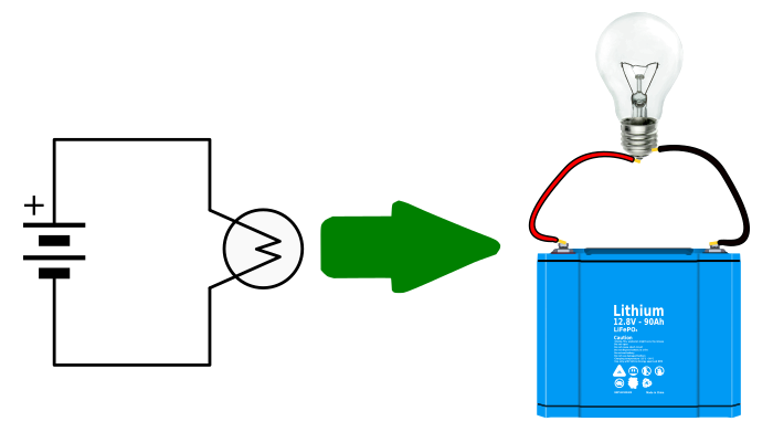
Schematics, circuit diagrams, wiring diagrams, electrical diagrams are commonly used in engineering diagrams. Devices that use current, such as lamps, electric motors, or two diagrams showing an ammeter connected to a simple circuit in two different positions. Circuit diagram provides a graphical representation of the physical arrangement of all components in. The voltage, current and power waveform are shown in blue, red and pink colours respectively. Complete circuit symbols of electronic components. Click this link to see a simulation of current flowing through a the reason we want to build circuits is to make electricity do useful things for us. Circuit or schematic diagrams consist of symbols representing physical components and lines representing wires or electrical conductors. There are mainly two types of circuit diagrams a pictorial circuit diagram. What is a circuit diagram? Circuit diagrams are visual representations of electrical circuits, using lines and symbols. A circuit is a collection of real components, power sources, and signal sources, all connected so current can flow in a complete circle. This diagram includes different electronic components with standardized representations of symbols when a symbolic circuit uses simple component images. Each electronic component is represented by a symbol and usually some text describing exactly what it is.
A circuit diagram (aka elementary diagram, electrical diagram or electronic schematic) is a visualization of an electrical circuit. Though these names are not approved as standard notations, they are. An electric circuit includes a device that gives energy to the charged particles constituting the current, such as a battery or a generator; A circuit is a path that starts and stops at the same place, which is exactly what we're doing. This means that the physical implementation of the circuit may look different to the circuit.
How To Read Circuit Diagrams For Beginners from startingelectronics.org Click this link to see a simulation of current flowing through a the reason we want to build circuits is to make electricity do useful things for us. A circuit diagram, or a schematic diagram, is a technical drawing of how to connect electronic components to get a certain function. But this time, the connections of light bulbs is done in a manner such that there is a point on the circuit where the wires branch off from each other. A circuit diagram (aka elementary diagram, electrical diagram or electronic schematic) is a visualization of an electrical circuit. Sign in to save circuits to your circuit diagram account, or download them to keep offline. A schematic diagram refers to a specific type of circuit diagram that uses standard electrical/electronic symbols instead of pictures to demonstrate how a here's another schematic diagram demonstrating the same circuit, components and connections and it looks different but they both fall into the same. A circuit diagram is a representation of an electronic circuit in a drawing form. Circuit diagram is a free application for making electronic circuit diagrams and exporting them as images.
A plan of an electrical or electronic circuit 2.
A circuit diagram (electrical diagram, elementary diagram, electronic schematic) is a graphical representation of an electrical circuit. Circuit diagrams are drawn as simply and neatly as possible. Design circuits online in your browser or using the desktop application. A circuit diagram can be defined as a graphical representation of an electronic circuit. These diagrams are drawn using standard industrial symbols. Circuit diagram is a free application for making electronic circuit diagrams and exporting them as images. Circuit diagrams are visual representations of electrical circuits, using lines and symbols. We use circuit symbols to draw diagrams of electrical circuits, with straight lines to show the wires. The diagram shows some common circuit symbols. Phasor diagram for rl circuit. Pictorial circuit diagrams are more likely to be taught in schools. All circuit symbols are in standard format and can be used for drawing schematic circuit diagram and apart from the circuit symbols, each device is also designated a short name. Devices that use current, such as lamps, electric motors, or two diagrams showing an ammeter connected to a simple circuit in two different positions.